Intro:
In part 1 of this project, I borrowed a Cadillac ATS caliper, a second generation Scion tC TRD caliper, and a DBA dual-drilled Subaru rotor. I tried several combinations of the three and came up empty-handed. When we left off, I was looking up rotors that were larger that could allow better fitment for the ATS caliper to the 7th Gen (2000-2005) front hub. I decided that a pair of Dodge Durango rotors might be a good option due to the price and being a thicker (32mm) rotor. It would also make this the a large 350mm (13.78″) off-the-shelf kit for the Celica.
Durango Rotors:
The Durango/Cherokee rotors arrived quickly (thanks, Jeff Bezos), and I immediately mounted them to my Bridgeport Mill and machined a 5x100mm bolt pattern:


In order, you can see me setting up the rotor on the mill, the completed modification, and a size comparison of the rotor with my hand. The first thing I noticed once mounting them is that both the Subaru rotor and the Durango rotor both clear the lower ball joint, but not by much. Any taller rotor height would be an issue, if anything, it’d be better to go to a shorter height rotor (more on that later).
When mounting the caliper, it became clear that either the ears on the caliper needed a trim, or the ears on the hub needed to be trimmed. Since you can’t reverse this modification, it’s typically better to modify the part the you’re adding to the car, so it is always reversible. So, with permission from Tom, I got the go ahead to do a quick trim to the caliper ears. I ended up removing about 0.160″ from the ears in order to clear the hub ears:


Bracket Fabrication:
Now that there was enough clearance between the ears of the hub and the ears of the caliper, it was time to fabricate the bracket to mount the two together:


As you can see, I used some cardboard-aided drafting (CAD, 😂) to get general dimensions and sizes for each of the mounting points and then got the radial dimensions and height differences and created an actual CAD model. The idea is that I can get the bracket water jetted and then finish mill the step-down (which provides a register for ease of installation). I’ve gotten a quote from an online water jetting company and the total cost for the bracket would be ~$150 for both brackets.
Revisions:
The best part about having a 3D Printer is that I can make revisions quickly. I made that cardboard template in the evening on a Sunday and had a final part (5 revisions later) the following evening. Most of the tweaks were very minor and iterative, but I was finally happy with the fit:


Version 5 (V5) fitment shown in the gallery above. Look closely and you can see the clearance between the rotor and the ball joint. The dimension that controls that is the rotor height, and if you were paying attention in Part 1, you’d know that there is a shorter rotor available that’s 350mm x 32mm (more on that later).
Job done, right?
Nope. It should’ve been that easy. Really, I was ready to get the bracket water jetted but I realized that there was still another issue. I had assumed that the ATS caliper was originally manufactured for the 355mm (14″) rotor because there are a ton of different “Cadillac Brembos”. This website does a decent job describing the various types.
Here’s a closer look at the issue where the caliper and rotor interfere:
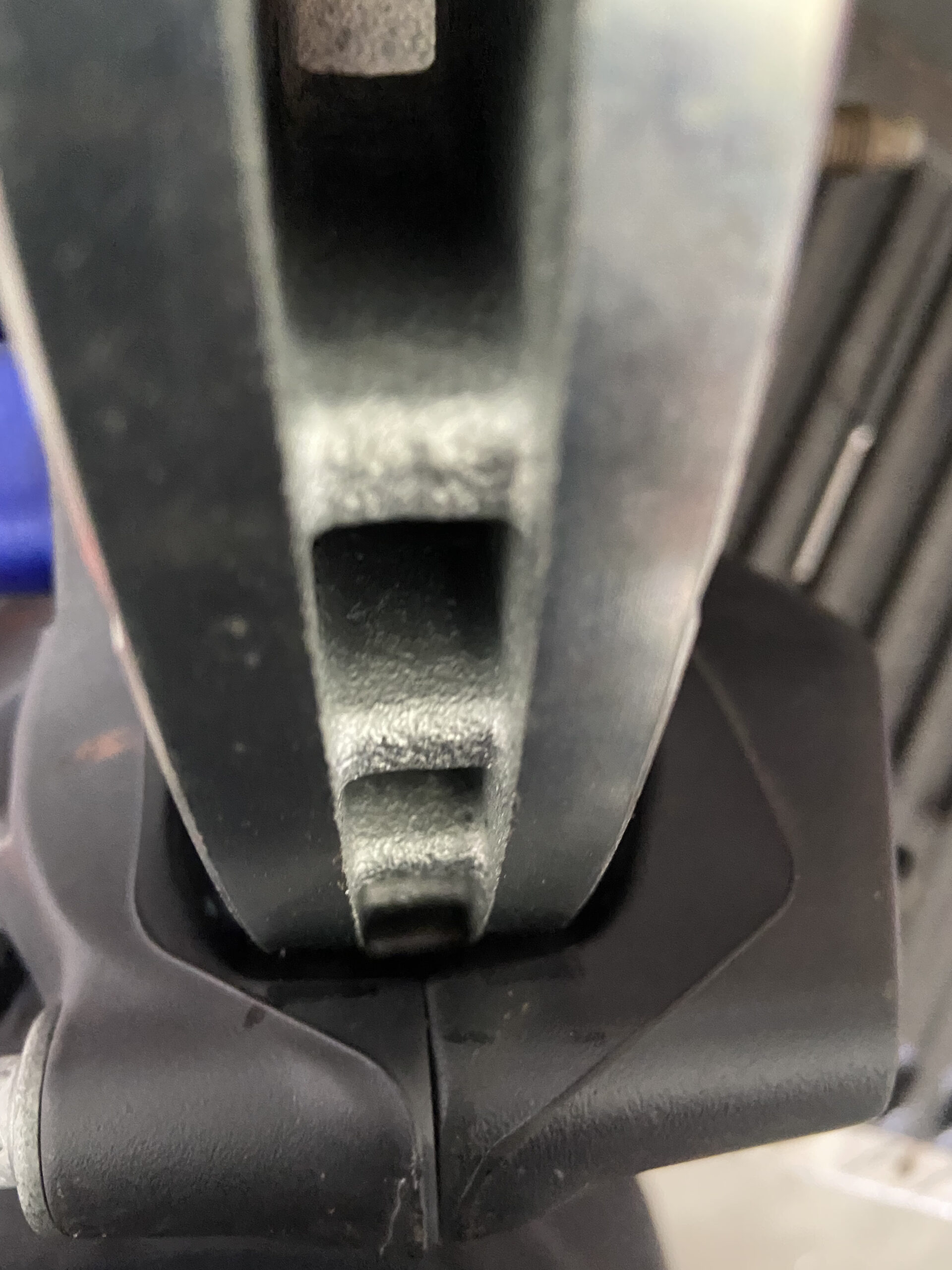
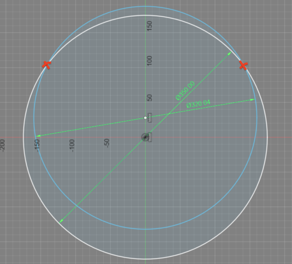
Let’s put two and two together. The original ATS Caliper was designed for a 12.6″ diameter rotor, as defined on the website that I linked above. I’m attempting to use a 350mm rotor (13.78″ in freedom units). The outer ends of the caliper are hitting the rotor due to the mismatch. I’m a visual person, so here’s a front-on representation of what is happening here (blue represents the designed caliper diameter, white is the 350mm rotor):
Outro:
Based on this, I felt that I had a few options:
- Machine the ATS caliper to clear the rotors. Upsides: still the cheapest calipers of the lot and the pads are still tall enough to grab the whole rotor face. Downsides: Could permanently damage the caliper (if fluid passage is breached), adds a more challenging machining operation to the modification (adds cost to kits), and the additional possibility that the caliper still wouldn’t have enough clearance after machining it.
- Buy one of the other inexpensive calipers. The 14″ CTS-V looks good as an alternative, as I wouldn’t have to worry about the diameters not matching. The biggest downside is that I would probably have to go through and redesign the bracket, but that’s not too bad.
- Order an aftermarket caliper and mount it to the one of my modified rotors.
Stay tuned because I’ll explore these options in the next post. Also, we’ll discuss what we’re going to do about the front/rear brake bias and the master cylinder sizing.